

D flip-flop captures the input data (D) only when a clock transition occurs—either on the rising edge (0 to 1) or the falling edge (1 to 0), depending on how it’s designed.
You might already be familiar with the D latch, and the D flip-flop works on a similar principle—but with one key difference: it responds to the edge of a clock signal rather than the signal’s level.As someone exploring digital electronics or VHDL coding, you’ve likely come across D flip-flops. In this post, I’ll help you understand what a D flip-flop is, how it functions, and how you can implement it using VHDL. We’ll also explore timing diagrams and different coding techniques to give you a complete picture.
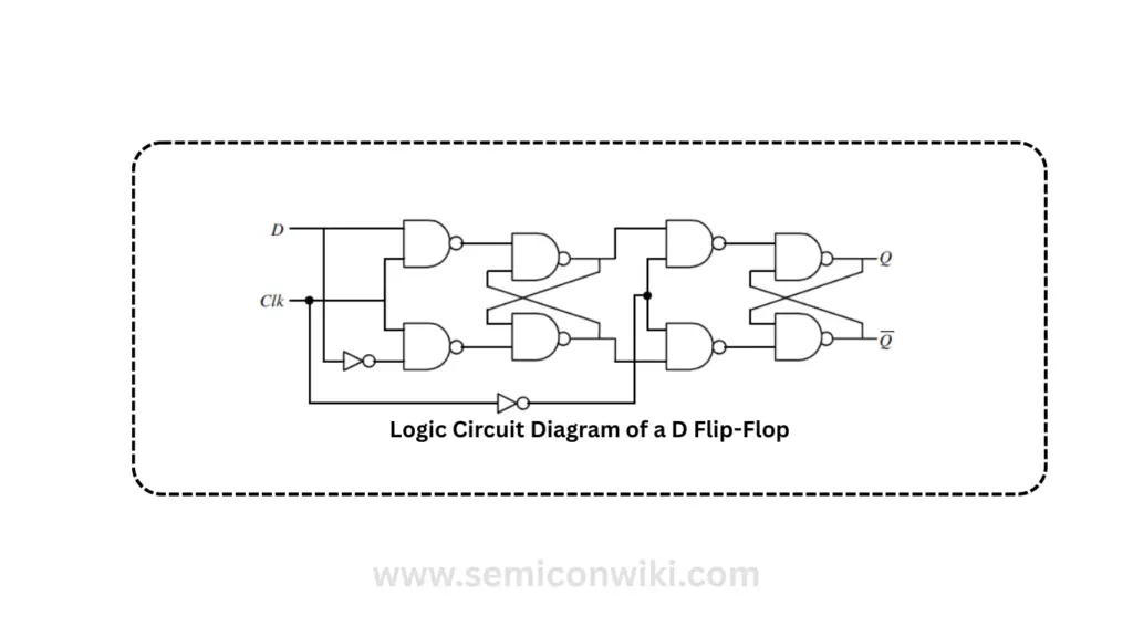
How a D Flip-Flop Works
Let’s break it down: the D flip-flop takes in a data input (D) and a clock signal (clk). When the clock signal transitions from 0 to 1 (rising edge), the flip-flop samples the value at D and passes it to the output Q.

Here’s how it behaves:
- If D is 1 when the clock rises, Q becomes 1.
- If D is 0, then Q is set to 0.
This behavior is incredibly useful when you want to store a fast-changing logic signal or synchronize it to a system clock.
VHDL Code for D Flip-Flop
Let me show you how you can implement this logic in VHDL. Here’s a simple version using an if statement to capture data on the rising edge of the clock:
library ieee;
use ieee.std_logic_1164.all;

entity D_flipflop is
    port (
        D, clk : in std_logic;
        Q      : out std_logic
    );
end D_flipflop;

architecture circuit_behavior of D_flipflop is
begin
    process (clk)
    begin
        if clk'event and clk = '1' then
            Q <= D;
        end if;
    end process;
end circuit_behavior;
In this code: clk’event and clk = ‘1’ ensures that the data is sampled on the positive edge of the clock. Q gets the value of D when this condition is met.
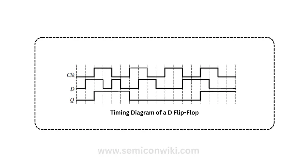
Timing Diagram of D Flip-Flop
Let’s say Q starts at 0. When the clock signal rises and D is high, the output Q also becomes high. If D is low at the clock edge, Q goes low. This pattern continues, and the output always reflects the input captured at the previous clock edge.
If you’re designing synchronous systems, the D flip-flop is your go-to tool for storing and synchronizing logic states. Whether you choose to implement it using if-then or wait until, both methods effectively achieve the same goal.
Read also: Crosstalk in VLSI
As you continue learning digital design or writing VHDL code, understanding these core concepts will give you a solid foundation. Try out both styles and see which fits your design flow better!