

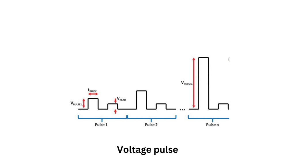
When a voltage pulse is applied to an interconnect, it creates an electric field in the interconnect. Let me explain how this works.
I’ve found that in a coaxial line without a dielectric, the positive voltage side of the pulse is applied to the center conductor. This results in an electric field that primarily goes from the center conductor to the outer conductor. This field is mainly transverse, meaning it’s directed across the line, but there’s also a small longitudinal component that runs along the line.
We often focus on the transverse electric field, ET, because it’s the dominant component. It’s calculated as the voltage across the distance between the conductors: VT = ET (a − b). This is usually sufficient for many applications, especially when the dimensions are small compared to the wavelength.
What are the roles of transverse and longitudinal Electric Fields?
However, you should also be aware of the longitudinal electric field, EL. Even though EL is small, it’s crucial for signal propagation along the line. At the beginning, when the voltage pulse is applied, EL is what starts to move electrons in the conductors. This creates current flow in the opposite direction to the electron movement. As the signal travels down the line, this longitudinal field helps maintain the current until the voltage drops to zero, at which point the signal eventually stops.
Read also: What is Fermi Level?
The energy of the signal moving along the line can be understood in two ways. One way is to look at how the current generates a magnetic field, and then calculate the energy based on the electric and magnetic fields. The other way, which works well at lower microwave frequencies, is to integrate the current and voltage over time to find the energy in the pulse.
In summary, the voltage pulse creates both transverse and longitudinal electric fields in the interconnect. While the transverse field is usually more significant, the longitudinal field is essential for moving the signal along the line. Understanding these fields helps us grasp how signals are transmitted and managed in interconnects.
Why Signal Integrity Matters in IC Design
When you’re working with integrated circuits (ICs), signal integrity becomes one of the most critical factors to watch. As designers, we aim to preserve the original shape and timing of a signal as it travels across the chip—without distortion or delay. If you lose signal integrity, the entire system’s performance can suffer.
In high-speed digital systems, timing is everything. Every operation depends on the signal arriving at just the right moment. If signal integrity is compromised, the signal might arrive too early or too late—or get so distorted that the receiving end can’t understand it. You might notice that the signal looks clean at the transmitting end but appears weak or noisy at the receiving end.
Factors like electromagnetic interference (EMI) and crosstalk between nearby wires are often responsible for this degradation. As you push for higher speeds and tighter layouts, maintaining signal integrity gets even more challenging—but also more important than ever.