


VLSI layout design, both Multiplier and Finger concepts are used to optimize transistor layout for better performance, area, and routing. Here’s the difference between the two:

What is Multiplier Concept in Layout?
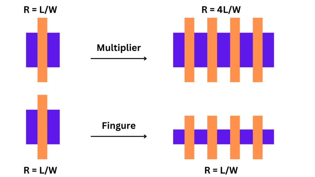
A multiplier refers to creating multiple instances (or copies) of a transistor and connecting them in parallel. If you have a multiplier of 4, it means 4 identical transistors are connected side by side. This increases the total current drive capability without changing the aspect ratio (W/L) of each transistor. It is typically used when higher drive strength is needed.
Use of Multiplier in Layout: Good for high current applications and helps reduce resistance by increasing the effective width of the device.
What is the Finger concept in Layout?
Fingers involve splitting a single large transistor into multiple smaller transistors (or “fingers”) and connecting them in parallel. Instead of having one large transistor, the width is divided into several parts. Each finger shares a common gate but has separate source and drain regions.
Use of Finger in Layout: Reduces the parasitic capacitance and improves speed by minimizing diffusion resistance, typically used for balancing power and performance.
Difference between Multiplier and Finger
Multiplier is about creating multiple instances of transistors, while Fingers split one transistor into smaller sections. Multiplier increases current capacity, whereas fingers improve performance and reduce parasitic in layout.
Read also: What is Body (Back Gate) Effect?
Single vs Multi-Finger MOSFET Layouts
When we design a MOSFET in an EDA tool, we usually face the choice between using a single-finger or a multi-finger (MF) layout. From my experience and what we’ve seen in practical design, each approach has its pros and cons — and the best choice depends on what you’re trying to achieve.
If you use a single-finger layout, it’s simple and easy to understand. But when the transistor has a large width, this layout becomes long and narrow, which can make routing and matching difficult. That’s where the multi-finger layout comes in handy.
By using multiple fingers, we can make the layout more compact and square-shaped. This gives us more flexibility, especially when we’re trying to fit the design within a limited area. Also, MF layouts help reduce gate resistance because the gate paths are effectively in parallel. This is really useful when you’re working with high-frequency signals since lower gate resistance means faster switching.
Another benefit is better matching between transistors, especially when using techniques like common-centroid layout, which is often important in analog design.
However, you should also know the downsides. In MF layouts, the current direction alternates between neighboring fingers, which can affect device performance slightly and lead to mismatches if not carefully handled. Also, the layout becomes more complex.
So, if you’re optimizing for speed, compactness, or matching, multi-finger layouts are often the way to go. But if you’re focused on simplicity and small devices, a single-finger layout might be enough. As designers, we always have to weigh these trade-offs based on what we need in the circuit.